Introducing PLANNet: A Smarter Way to Build Network Diagrams
Network diagrams are the backbone of IT documentation, but creating them can be a tedious chore. If you've ever wrestled with Visio stencils or nudged draw.io connectors into place, you know the struggle. Lines never quite stick where you want, and hunting down the right network stencils is an exercise in frustration and futility. In fact, one network engineer vented that Visio’s connector tool was “driving me insane, it never wants to link things properly”.
Enter PLANNet – a new network diagramming tool that promises to change all that. In this post, I want to introduce PLANNet and explore how it offers a smarter, faster way to build accurate network diagrams without generic templates or floating lines.
The Traditional Challenge: Diagrams with Floating Lines and Stencils
Before diving into PLANNet, let's acknowledge the pain points it aims to solve. Traditionally, diagramming a network means dragging generic symbols onto a canvas and drawing lines between them. Tools like Visio or Lucidchart provide libraries of shapes, but you often spend hours searching for the right stencil or manually labeling ports. Even then, the connections are merely lines attached to a shape, not to a specific port. Move a device icon and you risk leaving cables dangling or misaligned. It’s easy to end up with “floating” cable endpoints that don’t clearly indicate which ports are connected to what.
Consider a simple office network: a router connected to a switch, which connects to servers and access points. Using a generic diagram tool, you might use a router icon and a switch icon, then draw lines between them. But how do you show that the router’s Port 1 goes into the switch’s Port 24? You’d likely add text labels or hope the next person just knows which ports are used. As the network grows, keeping track of port-level details becomes nearly impossible with manual diagrams.
Meet plannet.work – A New Approach to Network Diagrams
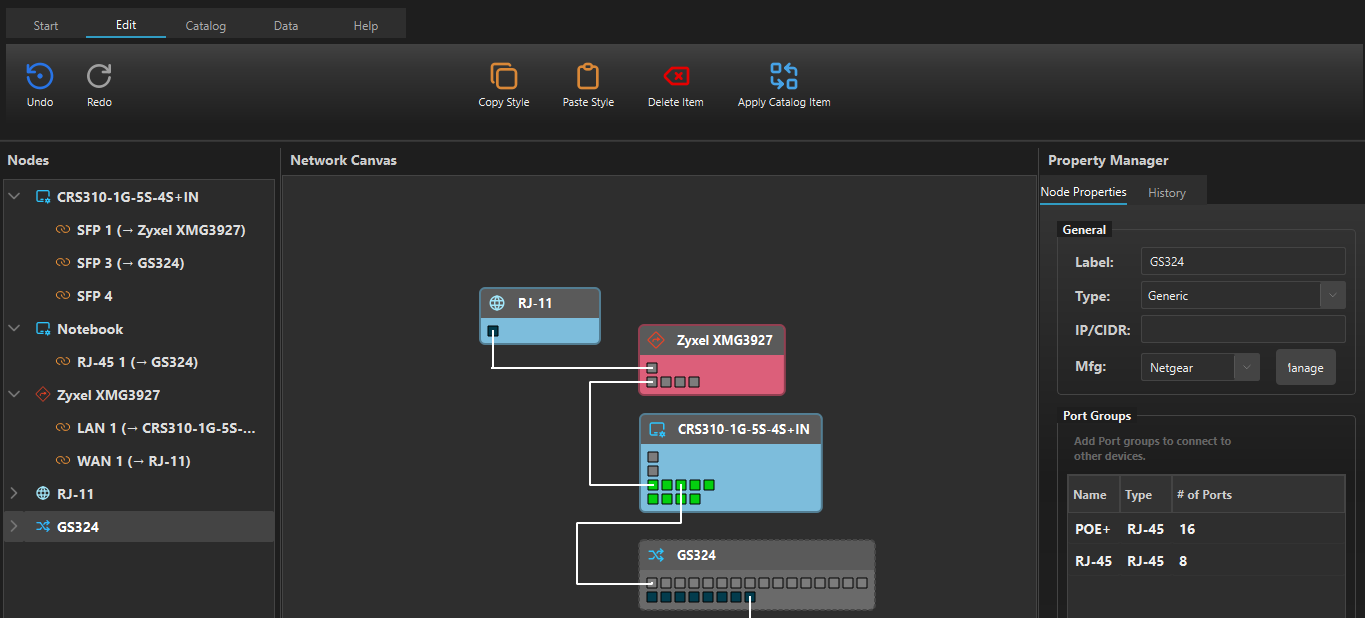
PLANNet is a visual network diagramming tool built with these challenges in mind. Instead of generic shapes and ad-hoc lines, PLANNet uses schematic node representations for network devices – by allowing you to configure the nodes with their actual port layouts. This means when you add a switch, you can then connect a link (cable), by dragging and dropping from one port to another, exactly as you would plug in a physical cable. The result? No more ambiguous connections or floating line endpoints. Every link snaps to a specific port on each device, making your diagram a precise map of how you want the network to be.
Here's an example of how this might look:

Unlike traditional diagram tools that rely on stencils or shape libraries, PLANNet works by allowing you to build your own device catalog. You can group network devices (routers, switches, firewalls, etc.) you created in your catalog, manage them by themselves, or add the nodes you configured in your diagram to the catalog. This eliminates the tedious search for the “right” stencil – you just quickly define your own device with the correct number of ports and layout. The focus is on having definite connections where necessary, rather than abstract "somehow this switch is connected to this firewall".
Finally, PLANNet isn’t just about drawing pretty pictures – it’s designed to be a practical network planning assistant. You can annotate each node, port, and link with rich information: IP addresses, MAC addresses, VLAN IDs, link speeds, cable types, and more. Your diagram becomes a living document of your network’s design. One of the features on the roadmap to 1.0 is the ability to generate a checklist of exactly what to connect where, turning your diagram into a deployment guide.
Real-World Example: Mapping a Home Lab Network
Imagine you're setting up a home lab with:
- A router for internet access
- A 24-port managed switch
- A NAS and a couple of servers
- A Wi-Fi access point
With PLANNet, your process might look like this:
- Scan or Add Devices – Discover active devices or add manually from catalog.
- Define Port Layouts – Assign ports to each node as per your setup.
- Drag-and-Drop Connections – Connect the correct ports visually.
- Annotate and Configure – Add IPs, VLANs, and other key metadata.
- Review the Plan – Visually confirm accuracy and layout.
- Export Connection List – Generate to-do list for physical deployment.
This way, you can plan what you need to do and create an installation plan you can reference when you actually implement your network.

Input & Feedback greatly appreciated
We've chosen to release this tool as a paid software, because we want to continue to continue to iterate on its functionality, but at the same time, we deeply believe in free software - so we've chosen to publish it under GPL3.
When you paid for the download of the signed binaries, you can request the source code from us, and we'll provide it so you can excercise your freedoms. (See the faq.)
PLANNet is currently available as a free beta until July 1, 2025. Download it now at plannet.work and start building your first diagram.
During the beta, all features currently implemented are available without restrictions. If you like what you see, you can support the project early and secure a discounted license for when 1.0 arrives.
Oh and: It’s a one-time purchase, no subscription.
Final Thoughts
This tool started out as a "How hard can it be?"-Question. I've struggled with quickly diagramming networks so many times, and especially when it needs to be quick, I've always reverted to paper because I was not quick enough to do it with draw.io. There are many diagramming tools that advertise themselves as "Network diagramming Tools", but to be honest - most of them are primarily diagramming tools with some network shapes.
I know that there are more integrated solutions like netbox and the topology plugin, but what I want - what I need - is the ability to draw a network diagram on the fly, without resorting to paper - and that's what this tool is.
Try the beta today, and see for yourself if this tool can help you. If you got feedback - there's a form here.